Current Transformers for Demand Controllers
A Current Transformer (CT) can use a demand controller and be interpreted as real kW. Current Transformers are mounted on the incoming electrical service mains between the utility meter and the main circuit breaker. They are used to monitor the total electric load, not just the loads connected to the Energy Sentry® demand controller.
Current transformers generate a current that is proportional to their turns ratio. This current can be read by the demand controller’s microcontroller and interpreted as real kW.
Energy Sentry demand controllers use 1000:1 turns for 200A CTs and 2000:1 turns for 400A CTs. Thus, for 200A Current Transformer, the output of each CT is one one-thousandth (1/1000th) of an amp, or 1 milliamp, for each ampere that passes through the mains. For 400A Current Transformer the output of each CT is one two-thousandth (1/2000th) of an amp, or 1/2 mA.
Two Current Transformers are usually mounted inside the load center. Most Energy Sentry installations use standard CTs that are shipped with each demand controller. However, certain installations require special Current Transformers in order to correctly adapt the Energy Sentry to the electrical service. The Current Transformers must be located so they monitor the total current of the utility service on which they are installed. They must measure the same current that the meter is measuring. See below for a brief description of the types of CTs available from Energy Sentry (Brayden Automation) and their proper application.
Hook-ups - Standard CT
The standard CT will easily fit up to 750 MCM cable (1.17 inches). Be sure the CT will fit in the load center with the cover in place. If there is not enough room in the load center, contact your utility company for the desired installation procedure. Installation of the current transformers must be done by a licensed electrician licensed in the jurisdiction where the controller is installed.
- Turn power OFF to the electrical service. This may require having the utility pull the meter or disconnect power to the service.
- Mount one CT on each of the incoming phase cables in the load center. Do this by installing the CTs around the main feeder cables between the meter and the main breaker. Make sure the CTs are mounted in the same direction.
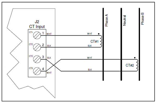
- Run the secondary wires to the 4-position terminal strip on the controller board assembly labeled “J2.” Leave about 6 to 8 inches extra. Do not run leads next to high-voltage (Class 1) wiring if possible. Keep the current transformer leads in the Class 2 compartment.
- Strip each conductor back 1/4 inch and connect black and white wires to 4-position terminal strip on the controller board assembly labeled either “CT1” or “CT2” as follows:
Terminal # Terminal Name Wire Color 1 (top) CT1 White - from CT1 2 CT1 Black - from CT1 3 CT2 White - from CT2 4 (bottom) CT2 Black - from CT2 - Route CT wires around the right side of the controller board assembly. Route all Class II wiring, including CT wires, through a separate knockout. Secure with a cable clamp at the knockout to provide strain relief.
Parallel Feeders
If an electrical service has parallel feeders, you may use two sets of CTs in parallel if the total input current does not exceed the current rating of the individual CTs. For example, if you have a 400A service consisting of two 200A panels and you are using two pairs of 200A CTs, the total current monitored by both pairs should never exceed 200A. If more than 200A, use two pairs of 400A CTs. See the Tech Tip on Parallel Current Transformers.
400A Large & Extra Large CTs
400A (double-ratio) CTs are designed for services up to 400 amperes. They also work when there are two service panels of 200A each. Hook up the secondary just as you hook up the standard CTs. Set the demand range (dr) to 80 KW for 400A CTs. It can also easily be done in the programming mode of the controller.
Warning
Before restoring power to the load center, be sure the secondary wires are secured to the controller board assembly. Otherwise, the CTs may be damaged. If the CTs cannot be connected to the controller board assembly, wire-nut the CT leads together. CTs “Like” a short circuit; they hate an open circuit.
Current Transformers Available from Brayden Automation
| Type | Max Amps | Turns Ratio | Range | dr Scale | Dimensions |
|---|---|---|---|---|---|
| Standard | 200A | 1000:1 | 48kW | 40 | 2.25 outside diameter (OD), 1.5 inside diameter (ID), 0.5 height (H) |
| Double Ratio Large | 400A | 2000:1 | 96kW | 80 | 2.75 OD, 1.75 ID, .75H |
| Double Ratio Extra-Large | 400A | 2000:1 | 96kW | 80 | 3.75 OD, 2.75 ID, 0.5H |
Note: The above table is for our most popular solid-core CTs. Split-Core CTs and other options available. Please call Brayden Automation at (888) 272-9336 to inquire.
for Dual Service